450/750V Mica+LSZH Insulated, Non-sheathed Power Cables to BS EN 50525-3-31 (Single Core)
FFX100 07mZ1-U/R/K (CU/MGT+LSZH 450/750V Class 1/2/5)
Application
The cables are mainly used in power stations, mass transit underground passenger systems, airports, petrochemical plants, hotels, hospitals and high-rise buildings.
Standards
Basic design adapted from BS EN 50525-3-31
Fire Performance
| Circuit Integrity | IEC 60331-21; BS 6387; BS 8491 |
| Flame Retardance (Single vertical wire or cable test) | IEC 60332-1-2; EN 60332-1-2 |
| Halogen free | IEC 60754-1; EN 50267-2-1 |
| No Corrosive Gas Emission | IEC60754-2; EN 50267-2-2 |
| Minimum Smoke Emission | IEC 61034-2; EN 61034-2 |
Voltage Rating
450/750V
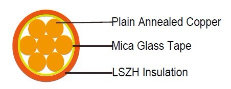
Cable Construction
Conductor: Copper conductor according to BS EN 60228 class 1/2/5.
FFX100 07mZ1-U: 1.5-10mm2 Class 1 solid copper conductor to BS EN 60228.
FFX100 07mZ1-R: 1.5-630mm2 Class 2 stranded copper conductor to BS EN 60228.
FFX100 07mZ1-K: 1.5-240mm2 Class 5 stranded copper conductor to BS EN 60228.
Fire Barrier: Mica glass tape.
Insulation: Thermoplastic compound of type TI 7 to EN 50363-7.
Insulation Option: UV resistance, hydrocarbon resistance, oil resistance, anti-rodent and anti-termite
properties can be offered as option.
Colour Code
Black, Blue, Brown, Grey, Orange, Pink, Red, Turquoise, Violet, White, Green and Yellow.
Physical And Thermal Properties
Maximum temperature range during operation: 70°C
Maximum short circuit temperature (5 Seconds): 160°C
Minimum bending radius:
OD<8mm: 4 × Overall Diameter
8mm≤OD≤12mm: 5 × Overall Diameter
OD>12mm: 6 × Overall Diameter
Construction Parameters
| Conductor | FFX100 07mZ1-U/R/K | ||||
|---|---|---|---|---|---|
| No. of Cores × Cross-sectional Area | Conductor Class | Nominal Insulation Thickness | Min. Overall Diameter | Max. Overall Diameter | Approx. Weight |
| No.×mm² | mm | mm | mm | kg/km | |
| 1×1.5 | 1 | 0.7 | 3.6 | 4.2 | 26 |
| 1×2.5 | 1 | 0.8 | 4.2 | 4.9 | 40 |
| 1×4 | 1 | 0.8 | 4.6 | 5.4 | 57 |
| 1×6 | 1 | 0.8 | 5.1 | 6.0 | 78 |
| 1×10 | 1 | 1.0 | 6.3 | 7.4 | 128 |
| 1×1.5 | 2 | 0.7 | 3.7 | 4.3 | 28 |
| 1×2.5 | 2 | 0.8 | 4.3 | 5.0 | 42 |
| 1×4 | 2 | 0.8 | 4.8 | 5.6 | 59 |
| 1×6 | 2 | 0.8 | 5.3 | 6.2 | 81 |
| 1×10 | 2 | 1.0 | 6.6 | 7.7 | 133 |
| 1×16 | 2 | 1.0 | 7.4 | 8.8 | 197 |
| 1×25 | 2 | 1.2 | 9.1 | 10.7 | 308 |
| 1×35 | 2 | 1.2 | 10.0 | 11.9 | 412 |
| 1×50 | 2 | 1.4 | 11.6 | 13.8 | 558 |
| 1×70 | 2 | 1.4 | 13.1 | 15.6 | 782 |
| 1×95 | 2 | 1.6 | 15.1 | 18.1 | 1078 |
| 1×120 | 2 | 1.6 | 16.6 | 19.8 | 1342 |
| 1×150 | 2 | 1.8 | 18.3 | 21.9 | 1650 |
| 1×185 | 2 | 2.0 | 20.3 | 24.3 | 2067 |
| 1×240 | 2 | 2.2 | 23 | 27.6 | 2703 |
| 1×300 | 2 | 2.4 | 25.5 | 30.6 | 3378 |
| 1×400 | 2 | 2.6 | 28.5 | 34.2 | 4267 |
| 1×500 | 2 | 2.8 | 31.5 | 37.9 | 5359 |
| 1×630 | 2 | 2.8 | 35 | 42.1 | 6884 |
| 1×1.5 | 5 | 0.7 | 3.8 | 4.4 | 27 |
| 1×2.5 | 5 | 0.8 | 4.4 | 5.1 | 42 |
| 1×4 | 5 | 0.8 | 4.9 | 5.8 | 59 |
| 1×6 | 5 | 0.8 | 5.4 | 6.3 | 81 |
| 1×10 | 5 | 1.0 | 6.7 | 7.8 | 134 |
| 1×16 | 5 | 1.0 | 7.7 | 9.1 | 197 |
| 1×25 | 5 | 1.2 | 9.4 | 11.2 | 304 |
| 1×35 | 5 | 1.2 | 10.7 | 12.7 | 410 |
| 1×50 | 5 | 1.4 | 12.5 | 14.9 | 585 |
| 1×70 | 5 | 1.4 | 14.2 | 17.0 | 811 |
| 1×95 | 5 | 1.6 | 16.1 | 19.2 | 1075 |
| 1×120 | 5 | 1.6 | 17.7 | 21.2 | 1341 |
| 1×150 | 5 | 1.8 | 19.6 | 23.5 | 1670 |
| 1×185 | 5 | 2.0 | 21.6 | 25.9 | 2042 |
| 1×240 | 5 | 2.2 | 24.5 | 29.4 | 2672 |
Electrical Properties
Conductor Operating Temperature : 70°C
Ambient Temperature : 30°C
Current-Carrying Capacities (Amp) according to BS 7671:2008 table 4D1A
| Conductor crosssection area |
Reference Method 4 (enclosed in conduit in thermally insulating wall etc) |
Reference Method 3 (enclosed in conduit on a wall or in trunking etc) |
Reference Method 1 (clipped direct) | Reference Method 11
(on a perforated cable
tray, horizontal or vertical) |
Reference Method 12 (free air) | ||||||
| Horizontal flat spaced | Vertical flat spaced | Trefoil | |||||||||
| 2 cables, single-phase a.c. or d.c. |
3 or 4 cables, 3-phase a.c. |
2 cables, single- |
3 or 4 cables, 3-phase a.c. |
2 cables, single-phase a.c. or d.c. flat and touching |
3 or 4 cables, 3-phase a.c. flat and touching or trefoil |
2 cables, single -phase a.c. or d.c. or flat and touching |
3 or 4 cables, 3-phase a.c. flat and touching or trefoil |
2 cables, single-phase a.c. or d.c. or 3 cables three phase |
2 cables, single-phase a.c. or d.c. or 3 cables three phase |
3 cables, trefoil 3-phase phase a.c. |
|
| phase a.c. a.c. or d.c |
|||||||||||
1 |
2 |
3 |
4 |
5 |
6 |
7 |
8 |
9 |
10 |
11 |
12 |
mm2 |
A |
A |
A |
A |
A |
A |
A |
A |
A |
A |
A |
1.5 |
18 |
17 |
22 |
19 |
25 |
23 |
- |
- |
- |
- |
- |
2.5 |
24 |
23 |
30 |
26 |
34 |
31 |
- |
- |
- |
- |
- |
4 |
33 |
30 |
40 |
35 |
46 |
41 |
- |
- |
- |
- |
- |
6 |
43 |
39 |
51 |
45 |
59 |
54 |
- |
- |
- |
- |
- |
10 |
58 |
53 |
71 |
63 |
81 |
74 |
- |
- |
- |
- |
- |
16 |
76 |
70 |
95 |
85 |
109 |
99 |
- |
- |
- |
- |
- |
25 |
100 |
91 |
126 |
111 |
143 |
130 |
158 |
140 |
183 |
163 |
138 |
35 |
125 |
111 |
156 |
138 |
176 |
161 |
195 |
176 |
226 |
203 |
171 |
50 |
149 |
135 |
189 |
168 |
228 |
209 |
293 |
215 |
274 |
246 |
209 |
70 |
189 |
170 |
240 |
214 |
293 |
268 |
308 |
279 |
351 |
318 |
270 |
95 |
228 |
205 |
290 |
259 |
355 |
326 |
375 |
341 |
426 |
389 |
330 |
120 |
263 |
235 |
336 |
299 |
413 |
379 |
436 |
398 |
495 |
453 |
385 |
150 |
300 |
270 |
375 |
328 |
476 |
436 |
505 |
461 |
570 |
524 |
445 |
185 |
341 |
306 |
426 |
370 |
545 |
500 |
579 |
530 |
651 |
600 |
511 |
240 |
400 |
358 |
500 |
433 |
644 |
590 |
686 |
630 |
769 |
711 |
606 |
300 |
459 |
410 |
573 |
493 |
743 |
681 |
794 |
730 |
886 |
824 |
701 |
400 |
- |
- |
684 |
584 |
868 |
793 |
915 |
849 |
1065 |
994 |
820 |
500 |
- |
- |
783 |
666 |
990 |
904 |
1044 |
973 |
1228 |
1150 |
936 |
630 |
- |
- |
900 |
764 |
1130 |
1033 |
1191 |
1115 |
1423 |
1338 |
1069 |
Voltage Drop (Per Amp Per Meter) according to BS 7671:2008 table 4D1B
| Nominal Cross Section Area |
2 cables d.c. |
2 cables, single-phase a.c. | 3 or 4 cables, 3-phase a.c. | |||||||||||||
| Ref. Methods 3 and 4 (enclosed in conduit etc, in or on a wall) |
Ref. Methods 1 and 11 (clipped direct or on trays touching) |
Ref. Methods 3 and 4 (enclosed in conduit etc, in or on a wall) |
Ref. Methods 1, | Ref. Methods 1 and 11 |
||||||||||||
| 11 and 12 (in trefoil) |
(Flat and touching) | |||||||||||||||
| 1 | 2 | 3 | 4 | 5 | 6 | 7 | ||||||||||
| mm2 | mV/A/m | mV/A/m | mV/A/m | mV/A/m | mV/A/m | mV/A/m | ||||||||||
1.5 |
31 |
|
31 |
|
|
27 |
|
|
27 |
|
|
27 |
|
|
27 |
|
2.5 |
19 |
|
19 |
|
|
16 |
|
|
16 |
|
|
16 |
|
|
16 |
|
4 |
33 |
|
12 |
|
|
10 |
|
|
10 |
|
|
10 |
|
|
10 |
|
6 |
7.8 |
|
7.9 |
|
|
6.8 |
|
|
6.8 |
|
|
6.8 |
|
|
6.8 |
|
10 |
4.7 |
|
4.7 |
|
|
4.7 |
|
|
4 |
|
|
4 |
|
|
4 |
|
16 |
2.9 |
|
2.9 |
|
|
2.9 |
|
|
2.5 |
|
|
2.5 |
|
|
2.5 |
|
|
|
r |
x |
z |
r |
x |
z |
r |
x |
z |
r |
x |
z |
r |
x |
z |
25 |
1.85 |
1.6 |
0.31 |
1.9 |
1.85 |
0.19 |
1.85 |
1.6 |
0.27 |
1.65 |
1.6 |
0.165 |
1.6 |
1.6 |
0.19 |
1.6 |
35 |
1.35 |
1.35 |
0.29 |
1.35 |
1.35 |
0.18 |
1.35 |
1.15 |
0.25 |
1.15 |
1.15 |
0.155 |
1.5 |
1.15 |
0.18 |
1.15 |
50 |
0.99 |
1 |
0.29 |
1.05 |
0.99 |
0.18 |
1 |
0.87 |
0.25 |
0.9 |
0.86 |
0.155 |
0.87 |
0.86 |
0.18 |
0.87 |
70 |
0.68 |
0.7 |
0.28 |
0.75 |
0.68 |
0.175 |
0.71 |
0.6 |
0.24 |
0.65 |
0.59 |
0.15 |
0.61 |
0.59 |
0.175 |
0.62 |
95 |
0.49 |
0.51 |
0.27 |
0.58 |
0.49 |
0.17 |
0.52 |
0.44 |
0.23 |
0.5 |
0.43 |
0.145 |
0.45 |
0.43 |
0.17 |
0.46 |
120 |
0.39 |
0.41 |
0.26 |
0.48 |
0.39 |
0.165 |
0.43 |
0.35 |
0.23 |
0.42 |
0.34 |
0.14 |
0.37 |
0.34 |
0.165 |
0.38 |
150 |
0.32 |
0.33 |
0.26 |
0.43 |
0.32 |
0.165 |
0.36 |
0.29 |
0.23 |
0.37 |
0.28 |
0.14 |
0.31 |
0.28 |
0.165 |
0.32 |
185 |
0.25 |
0.27 |
0.26 |
0.37 |
0.26 |
0.165 |
0.3 |
0.23 |
0.23 |
0.32 |
0.22 |
0.14 |
0.26 |
0.22 |
0.165 |
0.28 |
240 |
0.19 |
0.21 |
0.26 |
0.33 |
0.2 |
0.16 |
0.25 |
0.185 |
0.22 |
0.29 |
0.17 |
0.14 |
0.22 |
0.17 |
0.165 |
0.24 |
300 |
0.155 |
0.175 |
0.25 |
0.31 |
0.16 |
0.16 |
0.22 |
0.15 |
0.22 |
0.27 |
0.14 |
0.14 |
0.195 |
0.135 |
0.16 |
0.21 |
400 |
0.12 |
0.14 |
0.25 |
0.29 |
0.13 |
0.155 |
0.2 |
0.125 |
0.22 |
0.25 |
0.11 |
0.135 |
0.175 |
0.11 |
0.16 |
0.195 |
500 |
0.093 |
0.12 |
0.25 |
0.28 |
0.105 |
0.155 |
0.185 |
0.1 |
0.22 |
0.24 |
0.09 |
0.135 |
0.16 |
0.088 |
0.16 |
0.18 |
630 |
0.072 |
0.1 |
0.25 |
0.27 |
0.086 |
0.155 |
0.175 |
0.088 |
0.21 |
0.23 |
0.074 |
0.135 |
0.15 |
0.071 |
0.16 |
0.17 |
x = reactance
z = impedance
