Flame Retardant Central Loose Tube Fiber Optic cables
Application
These cables are characterized by light weight and small diameter, suitable for both aerial and duct
installation. They are mainly installed inside buildings, tunnels,subways or closed areas in general,
specially designed to guarantee the signal transmission even in case of fire. The cable can also be
used for direct burial for armoured version.
Standards
Basic design adapted to Telcordia GR-20 / RUS 7 CFR 1755.900 (REA PE-90) / ICEA S 87-640
Fire Performance
Flame Retardance (Single Vertical |
EN 60332-1-2; IEC 60332-1-2; BS EN 60332-1-2; VDE |
Reduced Fire Propagation |
EN 60332-3-24 (cat. C); IEC 60332-3-24; BS EN 60332-3-24; VDE 0482-332-3; NBN C 30-004 (cat. F2); NF C32-070-2.2(C1); CEI 20-22/3-4; EN 50266-2-4*; DIN VDE 0482-266-2-4 |
Note: Asterisk ** denotes that the standard compliance is optional, depending on the oxygen index of the PVC compound and the cable design.
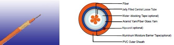
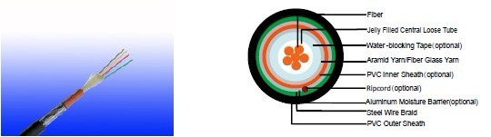
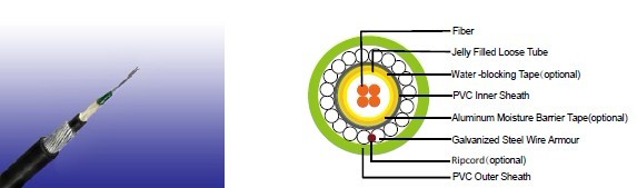
Cable Construction
Fibers: Singlemode and multimode fibers, with loose tube technology.
Structure: Central loose tube cable contains one tube with 2-24 single or multimode fibers, which
are filled with water blocking gel.
Water blocking: The jelly filled tube is waterblocked by using swellable tape and thread.
Reinforcement: Either aramid yarn or fiber glass is wound around the tube to provide physical
protection and tensile strength, with added fire protection.
Inner sheath (optional): The cable can be jacketed with either PE or thermoplastic PVC inner
sheath. PE is the preferred option in outdoor environment for water protection purpose.
Moisture Barrier Tape (optional): An aluminum moisture tape can be incorporated under the sheath
for water blocking and shielding purpose.
Armouring(optional):
For diect burial, either galvanized steel wire braid, corrugated steel tape armour or galvanized steel
wire armour is applied over an inner polyethylene or PVC sheath. For steel tape armour, the 0.15mm
thick steel tape is coated with a copolymer and applied with an overlap. For steel wire braid or
armour, single layer of galvanized steel wire braid or armour is applied.
Ripcord (optional): An optional ripcord can be located under the jacket to facilitate jacket removal.
Outer Sheath: Thermoplastic PVC compound. UV resistance, hydrocarbon resistance, oil resistance,
anti rodent and anti termite properties can be offered as option. Compliance to fire performance
standard (IEC 60332-1, IEC 60332-3, UL 1581, UL 1666 etc) depends on the oxygen index of the
PVC compound and the overall cable design. LSPVC can also be provided upon request.
Fiber colour code
Fiber colour code |
1 |
Red |
7 |
Brown |
|
2 |
Green |
8 |
Violet |
|
3 |
Blue |
9 |
Turquoise |
|
4 |
Yellow |
10 |
Black |
|
5 |
White |
11 |
Orange |
|
6 |
Grey |
12 |
Pink |
Construction
Unarmoured type
Construction Parameters
Cable Code |
Fiber |
Tube |
Nominal Overall Diameter |
Approx. Weight |
Tension load |
Crush |
|
(n°) |
mm |
mm |
kg/km |
N |
N/100mm |
CLA-B-C-Y-J |
02-06 |
2.7 |
8.0 |
70 |
1000 |
1500 |
CLA-B-C-Y-J |
08-16 |
3.5 |
9.0 |
90 |
1200 |
1500 |
CLA-B-C-Y-J |
18-24 |
4.2 |
10.0 |
100 |
1500 |
1500 |
Steel Wire Braid
Construction Parameters
Cable Code |
Fiber |
Tube |
Nominal Overall Diameter |
Approx. Weight |
Tension load |
Crush |
|
(n°) |
mm |
mm |
kg/km |
N |
N/100mm |
CLA-B-C-2Y(SWB)Y-J |
02-06 |
2.7 |
11.5 |
160 |
1000 |
2000 |
CLA-B-C-2Y(SWB)Y-J |
08-16 |
3.5 |
12.0 |
180 |
1200 |
2000 |
CLA-B-C-2Y(SWB)Y-J |
18-24 |
4.2 |
13.0 |
200 |
1500 |
2000 |
Corrugated Steel Tape Armour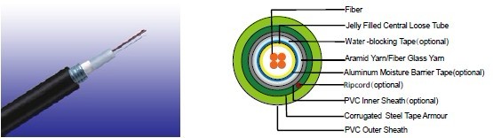
Construction Parameters
Cable Code |
Fiber |
Tube |
Diameter |
Approx. Weight |
Tension load |
Crush |
|
(n°) |
mm |
mm |
kg/km |
N |
N/100mm |
CLA-B-C-2Y(STA)Y-J |
02-06 |
2.7 |
13.0 |
200 |
1000 |
2500 |
CLA-B-C-2Y(STA)Y-J |
08-16 |
3.5 |
14.0 |
220 |
1200 |
2500 |
CLA-B-C-2Y(STA)Y-J |
18-24 |
4.2 |
14.5 |
250 |
1500 |
2500 |
Steel Wire armour
Construction Parameters
Cable Code |
Fiber |
Tube |
Nominal Overall Diameter |
Approx. Weight |
Tension load |
Crush |
|
(n°) |
mm |
mm |
kg/km |
N |
N/100mm |
CLA-B-C-2Y(SWA)Y-J |
02-12 |
2.7 |
10.5 |
180 |
2500 |
4000 |
CLA-B-C-2Y(SWA)Y-J |
16-24 |
3.5 |
11.0 |
210 |
2500 |
4000 |
Physical And Thermal Properties
Temperature range during operation (fixed state): -20°C - +60°C
Temperature range during installation (mobile state): 0°C - +50°C
Minimum operation Bending Radius: 10 times the outer diameter for unarmoured cables
20 times the outer diameter for armoured cables
Minimum Installation Bending Radius: 20 times the outer diameter
MechanIcal Properties
Maximum Compressive Load |
4000N for unarmoured cables |
Repeated Impact: |
4.4 N.m (J) |
Twist (Torsion): |
180×10 times, 125×OD |
Cyclic Flexing: |
25 cycles for armoured cables; |
Crush Resistance: |
263N/cm (150lb/in) |
Fiber Compliance
Temperature Cycling |
IEC60794-1-2-F2 |
Tensile Strength |
IEC60794-1-2-E1A |
Crush |
IEC60794-1-2-E3 |
Impact |
IEC60794-1-2-E4 |
Repeated Bending |
IEC60794-1-2-E6 |
Torsion |
IEC60794-1-2-E7 |
Kink |
IEC60794-1-2-E10 |
Cable Bend |
IEC60794-1-2-E11 |
Cool Bend |
IEC60794-1-2-E11 |
