600/1000V XLPE Insulated, LSZH Sheathed Power Cables to BS 8573 (2-5 Cores)
FTX400 1RZ1-R (CU/XLPE/LSZH 600/1000V Class 2)
Application
The cables are mainly used in power stations, mass transit underground passenger systems, airports,petrochemical plants, hotels, hospitals and high-rise buildings. This product type is TUV approved.
Standards
Basic design to BS 8573:2012
Fire Performance
Flame Retardance |
EN 60332-1-2; IEC 60332-1-2 |
Reduced Fire Propagation |
EN 60332-3-24 ; IEC 60332-3-24 |
Halogen Free |
IEC 60754-1; EN 50267-2-1 |
No Corrosive Gas Emission |
IEC 60754-2; EN 50267-2-2 |
Minimum Smoke Emission |
IEC 61034-2; EN 61034 -2; |
Voltage Rating
600/1000V
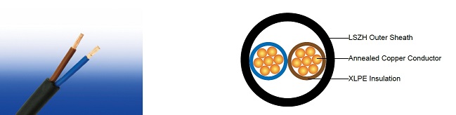
Cable Construction
Conductor: Annealed copper conductor, stranded according to BS EN 60228 class 2.
Insulation: Thermosetting insulation XLPE Type GP8 according to BS 7655-1.3. HEPR Type GP6 according to BS 7655-1.2 or crosslinked polyolefin material type EI 5 according to BS EN 50363-5 can be offered as option.
Inner Covering Option: The optional inner covering, where used, shall consist of an extruded layer of synthetic polymeric material. It shall surround the single core and the laid-up two, three, four or five cores, giving the assembly a practically circular shape.
Outer Sheath: Extruded layer of polymeric material LTS 4 according to BS 7655-6.1.
Outer Sheath Option: UV resistance, hydrocarbon resistance, oil resistance, anti-rodent and anti-termite properties can be offered as option.
Colour Code
| Insulation Colour | 2-core | Brown and blue. |
| 3-core | Brown, black and grey. | |
| Alternatively, green-and-yellow, blue, brown. | ||
| 4-core | Blue, brown black and grey. | |
| Alternatively, green-and-yellow, brown, black, grey. | ||
| 5-core | Green and yellow, blue, brown black, grey. | |
| Sheath Colour | Black; other colours can be offered upon request. | |
Construction Parameters
| Conductor | FTX400 1RZ1-R | |||||
|---|---|---|---|---|---|---|
| No. of Cores × Cross-sectional Area | Conductor Class | Nominal Insulation Thickness | Nominal Inner Covering Thickness | Nominal Sheath Thickness | Approx. Overall Diameter | Approx. Weight |
| No.×mm² | mm | mm | mm | mm | kg/km | |
| 2×1.5a | 2 | 0.7 | 0.4 | 1.8 | 9.6 | 117 |
| 2×2.5a | 2 | 0.7 | 0.4 | 1.8 | 10.4 | 146 |
| 2×4a | 2 | 0.7 | 0.4 | 1.8 | 11.5 | 190 |
| 2×6a | 2 | 0.7 | 0.4 | 1.8 | 12.6 | 244 |
| 2×10a | 2 | 0.7 | 0.6 | 1.8 | 14.5 | 349 |
| 2×16a | 2 | 0.7 | 0.6 | 1.8 | 16.6 | 495 |
| 2×25a | 2 | 0.9 | 0.8 | 1.8 | 20.0 | 735 |
| 2×35a | 2 | 0.9 | 0.8 | 1.8 | 22.3 | 963 |
| 2×50a | 2 | 1.0 | 1.0 | 1.8 | 25.4 | 1261 |
| 2×70a | 2 | 1.1 | 1.0 | 1.8 | 29.4 | 1751 |
| 2×95a | 2 | 1.1 | 1.2 | 1.9 | 33.4 | 2359 |
| 2×120a | 2 | 1.2 | 1.2 | 2.0 | 37.2 | 2950 |
| 2×25b | 2 | 0.9 | 0.6 | 1.8 | 16.1 | 692 |
| 2×35b | 2 | 0.9 | 0.6 | 1.8 | 17.9 | 913 |
| 2×50b | 2 | 1.0 | 0.8 | 1.8 | 20.6 | 1205 |
| 2×70b | 2 | 1.1 | 0.8 | 1.8 | 23.5 | 1680 |
| 2×95b | 2 | 1.1 | 1.0 | 1.9 | 26.2 | 2268 |
| 2×120b | 2 | 1.2 | 1.0 | 2.0 | 29.0 | 2838 |
| 3×1.5a | 2 | 0.7 | 0.4 | 1.8 | 10.0 | 143 |
| 3×2.5a | 2 | 0.7 | 0.4 | 1.8 | 10.9 | 183 |
| 3×4a | 2 | 0.7 | 0.4 | 1.8 | 12.1 | 244 |
| 3×6a | 2 | 0.7 | 0.4 | 1.8 | 13.3 | 321 |
| 3×10a | 2 | 0.7 | 0.6 | 1.8 | 15.3 | 472 |
| 3×16a | 2 | 0.7 | 0.6 | 1.8 | 17.6 | 681 |
| 3×25a | 2 | 0.9 | 0.8 | 1.8 | 21.3 | 1027 |
| 3×35a | 2 | 0.9 | 0.8 | 1.8 | 23.8 | 1360 |
| 3×50a | 2 | 1.0 | 1.0 | 1.8 | 27.1 | 1795 |
| 3×70a | 2 | 1.1 | 1.2 | 1.9 | 31.6 | 2530 |
| 3×95a | 2 | 1.1 | 1.2 | 2.0 | 36.1 | 3441 |
| 3×120a | 2 | 1.2 | 1.2 | 2.1 | 40.2 | 4307 |
| 3×25b | 2 | 0.9 | 0.6 | 1.8 | 18.5 | 993 |
| 3×35b | 2 | 0.9 | 0.8 | 1.8 | 21.1 | 1327 |
| 3×50b | 2 | 1.0 | 0.8 | 1.8 | 23.7 | 1751 |
| 3×70b | 2 | 1.1 | 1.0 | 1.9 | 27.6 | 2474 |
| 3×95b | 2 | 1.1 | 1.2 | 2.0 | 31.0 | 3364 |
| 3×120b | 2 | 1.2 | 1.2 | 2.1 | 33.8 | 4205 |
| 4×1.5a | 2 | 0.7 | 0.4 | 1.8 | 10.8 | 172 |
| 4×2.5a | 2 | 0.7 | 0.4 | 1.8 | 11.8 | 223 |
| 4×4a | 2 | 0.7 | 0.4 | 1.8 | 13.1 | 303 |
| 4×6a | 2 | 0.7 | 0.6 | 1.8 | 14.5 | 402 |
| 4×10a | 2 | 0.7 | 0.6 | 1.8 | 16.8 | 599 |
| 4×16a | 2 | 0.7 | 0.6 | 1.8 | 19.3 | 873 |
| 4×25a | 2 | 0.9 | 0.8 | 1.8 | 23.4 | 1328 |
| 4×35a | 2 | 0.9 | 1.0 | 1.8 | 26.2 | 1767 |
| 4×50a | 2 | 1.0 | 1.0 | 1.8 | 29.9 | 2339 |
| 4×70a | 2 | 1.1 | 1.2 | 2.0 | 35.1 | 3326 |
| 4×95a | 2 | 1.1 | 1.2 | 2.1 | 39.9 | 4505 |
| 4×120a | 2 | 1.2 | 1.2 | 2.3 | 44.7 | 5669 |
| 4×25b | 2 | 0.9 | 0.8 | 1.8 | 18.8 | 1293 |
| 4×35b | 2 | 0.9 | 0.8 | 1.8 | 21.1 | 1727 |
| 4×50b | 2 | 1.0 | 1.0 | 1.8 | 24.2 | 2296 |
| 4×70b | 2 | 1.1 | 1.2 | 2.0 | 27.6 | 3258 |
| 4×95b | 2 | 1.1 | 1.2 | 2.1 | 30.7 | 4409 |
| 4×120b | 2 | 1.2 | 1.2 | 2.3 | 34.0 | 5549 |
| 5×1.5a | 2 | 0.7 | 0.4 | 1.8 | 10.8 | 172 |
| 5×2.5a | 2 | 0.7 | 0.4 | 1.8 | 11.8 | 223 |
| 5×4a | 2 | 0.7 | 0.6 | 1.8 | 14.2 | 367 |
| 5×6a | 2 | 0.7 | 0.6 | 1.8 | 15.8 | 492 |
| 5×10b | 2 | 0.7 | 0.6 | 1.8 | 17.5 | 754 |
| 5×16b | 2 | 0.7 | 0.8 | 1.8 | 21.6 | 1141 |
| 5×25b | 2 | 0.9 | 1.0 | 1.8 | 24.6 | 1678 |
| 5×35b | 2 | 0.9 | 1.0 | 1.8 | 28.2 | 2273 |
| 5×50b | 2 | 1.0 | 1.2 | 1.9 | 31.9 | 3000 |
| 5×70b | 2 | 1.1 | 1.2 | 2.1 | 35.7 | 4187 |
| 5×95b | 2 | 1.1 | 1.4 | 2.2 | 41.0 | 5748 |
| 5×120b | 2 | 1.2 | 1.4 | 2.4 | 44.2 | 7142 |
Electrical Properties
Maximum temperature range during operation: 90°C
Maximum short circuit temperature (5 Seconds): 250°C
Minimum bending radius
circular copper conductors OD≤25mm : 4 × Overall Diameter
circular copper conductors OD﹥25mm : 6 × Overall Diameter
shaped copper conductors : 8 × Overall Diameter
Current-Carrying Capacities (Amp) according to BS 7671:2008 table 4E2A
| Conductor cross-sectional area | Ref. Method A (enclosed in conduit in thermally insulating wall etc.) | Ref. Method B (enclosed in conduit on a wall or in trunking etc.) | Ref. Method C (clipped direct) | Ref. Method E (in free air or on a perforated cable tray etc. horizontal or vertical) | ||||
|---|---|---|---|---|---|---|---|---|
| 1 two-core cable*, single-phase a.c. or d.c. | 1 three- or four-core cable*, three-phase a.c. | 1 two-core cable*, single-phase a.c. or d.c. | 1 three- or four-core cable*, three-phase a.c. | 1 two-core cable*, single-phase a.c. or d.c. | 1 three- or four-core cable*, three-phase a.c. | 1 two-core cable*, single-phase a.c. or d.c. | 1 three- or four-core cable*, three-phase a.c. | |
| 1 | 2 | 3 | 4 | 5 | 6 | 7 | 8 | 9 |
| mm² | A | A | A | A | A | A | A | A |
| 1.5 | 18.5 | 16.5 | 22 | 19.5 | 24 | 22 | 26 | 23 |
| 2.5 | 25 | 22 | 30 | 26 | 33 | 30 | 36 | 32 |
| 4 | 33 | 30 | 40 | 35 | 45 | 40 | 49 | 42 |
| 6 | 42 | 38 | 51 | 44 | 58 | 52 | 63 | 54 |
| 10 | 57 | 51 | 69 | 60 | 80 | 71 | 86 | 75 |
| 16 | 76 | 68 | 91 | 80 | 107 | 96 | 115 | 100 |
| 25 | 99 | 89 | 119 | 105 | 138 | 119 | 149 | 127 |
| 35 | 121 | 109 | 146 | 128 | 171 | 147 | 185 | 158 |
| 50 | 145 | 130 | 175 | 154 | 209 | 179 | 225 | 192 |
| 70 | 183 | 164 | 221 | 194 | 269 | 229 | 289 | 246 |
| 95 | 220 | 197 | 265 | 233 | 328 | 278 | 352 | 298 |
| 120 | 253 | 227 | 305 | 268 | 382 | 322 | 410 | 346 |
Note: With or without a protective conductor.
Voltage Drop (Per Amp Per Meter) according to BS 7671:2008 table 4E2B
| Conductor cross-sectional area | Two-core cable, d.c. | Two-core cable, single-phase a.c. | Three- or four-core cable, three-phase a.c. | ||||
|---|---|---|---|---|---|---|---|
| 1 | 2 | 3 | 4 | ||||
| mm² | mV/A/m | mV/A/m | mV/A/m | ||||
| 1.5 | 31 | 31 | 27 | ||||
| 2.5 | 19 | 19 | 16 | ||||
| 4 | 12 | 12 | 10 | ||||
| 6 | 7.9 | 7.9 | 6.8 | ||||
| 10 | 4.7 | 4.7 | 4.0 | ||||
| 16 | 2.9 | 2.9 | 2.5 | ||||
| r | x | z | r | x | z | ||
| 25 | 1.85 | 1.85 | 0.160 | 1.90 | 1.60 | 0.140 | 1.65 |
| 35 | 1.35 | 1.35 | 0.155 | 1.35 | 1.15 | 0.135 | 1.15 |
| 50 | 0.98 | 0.99 | 0.155 | 1.00 | 0.86 | 0.135 | 0.87 |
| 70 | 0.67 | 0.67 | 0.150 | 0.69 | 0.59 | 0.130 | 0.60 |
| 95 | 0.49 | 0.50 | 0.150 | 0.52 | 0.43 | 0.130 | 0.45 |
| 120 | 0.39 | 0.40 | 0.145 | 0.42 | 0.34 | 0.130 | 0.37 |
Note :
r = conductor resistance at operating temperature
x = reactance
z = impedance
