600/1000V XLPE Insulated, LSZH Sheathed, Armoured Power Cables to BS 6724 (2-5 Cores)
FTX400 1RZ1MZ1-R (CU/XLPE/LSZH/SWA/LSZH 600/1000V Class 2)
Application
The cables is mainly used in power stations, mass transit underground passenger systems, airports, petrochemical plants, hotels, hospitals, and high-rise buildings.This product type is TUV approved.
Standards
Basic design to BS 6724
Fire Performance
Flame Retardance |
EN 60332-1-2; IEC 60332-1-2 |
Reduced Fire Propagation |
EN 60332-3-24 ; IEC 60332-3-24 |
Halogen Free |
IEC 60754-1; EN 50267-2-1 |
No Corrosive Gas Emission |
IEC 60754-2; EN 50267-2-2 |
Minimum Smoke Emission |
IEC 61034-2; EN 61034 -2 |
Voltage Rating
600/1000V
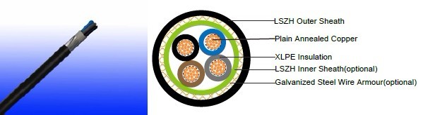
Cable Construction
Conductor:Annealed copper wire, stranded according to BS EN 60228 class 2.
Insulation: XLPE type GP8 according to BS 7655-1.3. HEPR type GP6 according to BS 7655-1.2 or crosslinked polyolefin material type EI 5 according to BS EN 50363-5 can be offered as option.
Bedding: Extruded layer of polymeric material.
Armouring: Galvanized steel wire.
Outer Sheath: Extruded layer of polymeric material LTS 1 according to BS 7655-6.1.
Outer Sheath Option: UV resistance, hydrocarbon resistance, oil resistance, anti-rodent and anti-termite properties can be offered as option.
Colour Code
| Insulation Colour | 2-core | Brown and blue. |
| 3-core | Brown, black and grey. | |
| 4-core | Blue, brown black and grey. | |
| 5-core | Green and yellow, blue, brown black, grey. | |
| Other colours can be offered upon request. | ||
| Sheath Colour | Black; other colours can be offered upon request. | |
Physical And Thermal Properties
Maximum temperature range during operation: 90°C
Maximum short circuit temperature (5 Seconds): 250°C
Minimum bending radius
circular copper conductors : 6 × Overall Diameter
shaped copper conductors : 8 × Overall Diameter
Construction Parameters
| Conductor | FTX400 1RZ1MZ1-R | ||||||
|---|---|---|---|---|---|---|---|
| No. of Cores × Cross-sectional Area | Conductor Class | Nominal Insulation Thickness | Nominal Bedding Thickness | Nominal Steel Wire Armour Diameter | Nominal Sheath Thickness | Approx. Overall Diameter | Approx. Weight |
| No.×mm² | mm | mm | mm | mm | mm | kg/km | |
| 2 Cores | |||||||
| 2×1.5a | 2 | 0.6 | 0.8 | 0.9 | 1.3 | 12.1 | 294 |
| 2×2.5a | 2 | 0.7 | 0.8 | 0.9 | 1.4 | 13.6 | 354 |
| 2×4a | 2 | 0.7 | 0.8 | 0.9 | 1.4 | 14.7 | 420 |
| 2×6a | 2 | 0.7 | 0.8 | 0.9 | 1.4 | 15.9 | 497 |
| 2×10a | 2 | 0.7 | 0.8 | 0.9 | 1.5 | 18.0 | 650 |
| 2×16a | 2 | 0.7 | 0.8 | 1.25 | 1.5 | 20.4 | 964 |
| 2×25a | 2 | 0.9 | 0.8 | 1.25 | 1.6 | 24.1 | 1314 |
| 2×25b | 2 | 0.9 | 0.8 | 1.25 | 1.6 | 20.4 | 1254 |
| 2×35a | 2 | 0.9 | 1.0 | 1.6 | 1.7 | 27.7 | 1832 |
| 2×35b | 2 | 0.9 | 1.0 | 1.6 | 1.7 | 23.3 | 1736 |
| 2×50b | 2 | 1.0 | 1.0 | 1.6 | 1.8 | 25.8 | 2261 |
| 2×70b | 2 | 1.1 | 1.0 | 1.6 | 1.9 | 29.0 | 2922 |
| 2×95b | 2 | 1.1 | 1.2 | 2.0 | 2.0 | 33.1 | 4029 |
| 2×120b | 2 | 1.2 | 1.2 | 2.0 | 2.1 | 36.1 | 4796 |
| 2×150b | 2 | 1.4 | 1.2 | 2.0 | 2.2 | 39.3 | 5646 |
| 2×185b | 2 | 1.6 | 1.4 | 2.5 | 2.4 | 44.7 | 7365 |
| 2×240b | 2 | 1.7 | 1.4 | 2.5 | 2.5 | 49.0 | 9027 |
| 2×300b | 2 | 1.8 | 1.6 | 2.5 | 2.6 | 53.5 | 10832 |
| 2×400b | 2 | 2.0 | 1.6 | 2.5 | 2.8 | 59.0 | 13216 |
| 3 cores | |||||||
| 3×1.5a | 2 | 0.6 | 0.8 | 0.9 | 1.3 | 12.6 | 320 |
| 3×2.5a | 2 | 0.7 | 0.8 | 0.9 | 1.4 | 14.1 | 401 |
| 3×4a | 2 | 0.7 | 0.8 | 0.9 | 1.4 | 15.3 | 487 |
| 3×6a | 2 | 0.7 | 0.8 | 0.9 | 1.4 | 16.6 | 588 |
| 3×10a | 2 | 0.7 | 0.8 | 1.25 | 1.5 | 19.5 | 906 |
| 3×16a | 2 | 0.7 | 0.8 | 1.25 | 1.6 | 21.6 | 1190 |
| 3×25a | 2 | 0.9 | 1.0 | 1.6 | 1.7 | 26.7 | 1858 |
| 3×25b | 2 | 0.9 | 1.0 | 1.6 | 1.7 | 23.6 | 1755 |
| 3×35a | 2 | 0.9 | 1.0 | 1.6 | 1.8 | 29.4 | 2298 |
| 3×35b | 2 | 0.9 | 1.0 | 1.6 | 1.8 | 25.7 | 2154 |
| 3×50b | 2 | 1.0 | 1.0 | 1.6 | 1.8 | 28.5 | 2858 |
| 3×70b | 2 | 1.1 | 1.0 | 1.6 | 1.9 | 32.2 | 3761 |
| 3×95b | 2 | 1.1 | 1.2 | 2.0 | 2.1 | 37.0 | 5204 |
| 3×120b | 2 | 1.2 | 1.2 | 2.0 | 2.2 | 40.4 | 6258 |
| 3×150b | 2 | 1.4 | 1.4 | 2.5 | 2.3 | 45.5 | 7989 |
| 3×185b | 2 | 1.6 | 1.4 | 2.5 | 2.4 | 49.8 | 9586 |
| 3×240b | 2 | 1.7 | 1.4 | 2.5 | 2.6 | 55.1 | 11930 |
| 3×300b | 2 | 1.8 | 1.6 | 2.5 | 2.7 | 60.2 | 14427 |
| 3×400b | 2 | 2.0 | 1.6 | 2.5 | 2.9 | 66.6 | 17765 |
| 4 cores | |||||||
| 4×1.5a | 2 | 0.6 | 0.8 | 0.9 | 1.3 | 13.3 | 388 |
| 4×2.5a | 2 | 0.7 | 0.8 | 0.9 | 1.4 | 15.0 | 460 |
| 4×4a | 2 | 0.7 | 0.8 | 0.9 | 1.4 | 16.4 | 566 |
| 4×6a | 2 | 0.7 | 0.8 | 1.25 | 1.5 | 18.7 | 813 |
| 4×10a | 2 | 0.7 | 0.8 | 1.25 | 1.5 | 21.1 | 1073 |
| 4×16a | 2 | 0.7 | 0.8 | 1.25 | 1.6 | 23.4 | 1431 |
| 4×25a | 2 | 0.9 | 1.0 | 1.6 | 1.7 | 28.9 | 2239 |
| 4×25b | 2 | 0.9 | 1.0 | 1.6 | 1.7 | 26.1 | 2102 |
| 4×35a | 2 | 0.9 | 1.0 | 1.6 | 1.8 | 31.9 | 2797 |
| 4×35b | 2 | 0.9 | 1.0 | 1.6 | 1.8 | 28.6 | 2606 |
| 4×50b | 2 | 1.0 | 1.0 | 1.6 | 1.9 | 32.0 | 3530 |
| 4×70b | 2 | 1.1 | 1.2 | 2.0 | 2.1 | 37.7 | 5074 |
| 4×95b | 2 | 1.1 | 1.2 | 2.0 | 2.2 | 41.7 | 6474 |
| 4×120b | 2 | 1.2 | 1.4 | 2.5 | 2.3 | 47.1 | 8390 |
| 4×150b | 2 | 1.4 | 1.4 | 2.5 | 2.4 | 51.4 | 9947 |
| 4×185b | 2 | 1.6 | 1.4 | 2.5 | 2.6 | 56.6 | 12096 |
| 4×240b | 2 | 1.7 | 1.6 | 2.5 | 2.7 | 63.0 | 15109 |
| 4×300b | 2 | 1.8 | 1.6 | 2.5 | 2.9 | 68.8 | 18276 |
| 4×400b | 2 | 2.0 | 1.8 | 3.15 | 3.2 | 78.1 | 23849 |
| 5 cores | |||||||
| 5×1.5a | 2 | 0.6 | 0.8 | 0.9 | 1.4 | 14.3 | 413 |
| 5×2.5a | 2 | 0.7 | 0.8 | 0.9 | 1.4 | 16.1 | 521 |
| 5×4a | 2 | 0.7 | 0.8 | 0.9 | 1.5 | 17.8 | 658 |
| 5×6a | 2 | 0.7 | 0.8 | 1.25 | 1.5 | 20 | 932 |
| 5×10a | 2 | 0.7 | 0.8 | 1.25 | 1.6 | 22.9 | 1258 |
| 5×16a | 2 | 0.7 | 1.0 | 1.6 | 1.7 | 26.6 | 1893 |
| 5×25a | 2 | 0.9 | 1.0 | 1.6 | 1.8 | 31.5 | 2646 |
| 5×35a | 2 | 0.9 | 1.0 | 1.6 | 1.9 | 34.8 | 3326 |
| 5×50a | 2 | 1.0 | 1.2 | 2 | 2 | 40.4 | 4567 |
| 5×70a | 2 | 1.1 | 1.2 | 2 | 2.2 | 46.3 | 6056 |
a Circular or compacted circular stranded conductors (class 2).
b Shaped stranded conductor (class 2).
Electrical Properties
Conductor Operating Temperature : 90°C
Air ambient temperature : 30°C
Ground ambient temperature : 20°C
Current-Carrying Capacities (Amp) according to BS 7671:2008 table 4E4A
| Conductor cross-ectional area | Ref. Method C (clipped direct) | Ref. Method E (in free air or on a perforated cable tray etc. horizontal or vertical) | Ref. Method D (direct in in groud or in ducting in groud. in or around buildings) | |||
|---|---|---|---|---|---|---|
| 1 two-core cable, single-phase a.c. or d.c. | 1 three- or four-core cable, three-phase a.c. | 1 two-core cable, single-phase a.c. or d.c. | 1 three- or four-core cable, three-phase a.c. | 1 two-core cable, single-phase a.c. or d.c. | 1 three- or four-core cable, three-phase a.c. | |
| 1 | 2 | 3 | 4 | 5 | 6 | 7 |
| mm² | A | A | A | A | A | A |
| 1.5 | 27 | 23 | 29 | 25 | 25 | 21 |
| 2.5 | 36 | 31 | 39 | 33 | 33 | 28 |
| 4 | 49 | 42 | 52 | 44 | 43 | 36 |
| 6 | 62 | 53 | 66 | 56 | 53 | 44 |
| 10 | 85 | 73 | 90 | 78 | 71 | 58 |
| 16 | 110 | 94 | 115 | 99 | 91 | 75 |
| 25 | 146 | 124 | 152 | 131 | 116 | 96 |
| 35 | 180 | 154 | 188 | 162 | 139 | 115 |
| 50 | 219 | 187 | 228 | 197 | 164 | 135 |
| 70 | 279 | 238 | 291 | 251 | 203 | 167 |
| 95 | 338 | 289 | 354 | 304 | 239 | 197 |
| 120 | 392 | 335 | 410 | 353 | 271 | 223 |
| 150 | 451 | 386 | 472 | 406 | 306 | 251 |
| 185 | 515 | 441 | 539 | 463 | 343 | 281 |
| 240 | 607 | 520 | 636 | 546 | 395 | 324 |
| 300 | 698 | 599 | 732 | 628 | 446 | 365 |
| 400 | 787 | 673 | 847 | 728 | - | - |
Voltage Drop (Per Amp Per Meter) according to BS 7671:2008 table 4E4B
| Conductor cross-sectional area | Two-core cable, d.c. | Two-core cable, single-phase a.c. | Three- or four-core cable, three-phase a.c. | ||||
|---|---|---|---|---|---|---|---|
| 1 | 2 | 3 | 4 | ||||
| mm² | mV/A/m | mV/A/m | mV/A/m | ||||
| 1.5 | 31 | 31 | 27 | ||||
| 2.5 | 19 | 19 | 16 | ||||
| 4 | 12 | 12 | 10 | ||||
| 6 | 7.9 | 7.9 | 6.8 | ||||
| 10 | 4.7 | 4.7 | 4.0 | ||||
| 16 | 2.9 | 2.9 | 2.5 | ||||
| r | x | z | r | x | z | ||
| 25 | 1.85 | 1.85 | 0.160 | 1.90 | 1.60 | 0.140 | 1.65 |
| 35 | 1.35 | 1.35 | 0.155 | 1.35 | 1.15 | 0.135 | 1.15 |
| 50 | 0.98 | 0.99 | 0.155 | 1.00 | 0.86 | 0.135 | 0.87 |
| 70 | 0.67 | 0.67 | 0.150 | 0.69 | 0.59 | 0.130 | 0.60 |
| 95 | 0.49 | 0.50 | 0.150 | 0.52 | 0.43 | 0.130 | 0.45 |
| 120 | 0.39 | 0.40 | 0.145 | 0.42 | 0.34 | 0.130 | 0.37 |
| 150 | 0.31 | 0.32 | 0.145 | 0.35 | 0.38 | 0.125 | 0.30 |
| 185 | 0.25 | 0.26 | 0.145 | 0.29 | 0.22 | 0.125 | 0.26 |
| 240 | 0.195 | 0.200 | 0.140 | 0.24 | 0.175 | 0.125 | 0.21 |
| 300 | 0.155 | 0.160 | 0.140 | 0.21 | 0.140 | 0.120 | 0.185 |
| 400 | 0.120 | 0.130 | 0.140 | 0.190 | 0.115 | 0.120 | 0.165 |
Note :
r = conductor resistance at operating temperature
x = reactance
z = impedance
