Cat 6 SF/UTP 24AWG 4P/8P
Applications
These Cat6 SF/UTP cables are manufactured in accordance with IEC 61156-5 requirements, can support all Class E applications like Ethernet, Fast Ethernet, Gigabit Ethernet, suitable for basic voice and data installations up to 250MHz.
Standards
- EN 50288
- ISO 11801
- IEC 61156-5
- IEC 60332-1
- IEC 60754-1/2
- IEC 61034
Construction
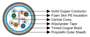
| Central Cross | |
| Conductors | Solid bare copper conductor. |
| Insulation | Foam skin PE. |
| Twinning | Two coloured insulated conductors twisted together to form a pair. |
| Overall Screen1 | Al/polyester tape. |
| Overall Screen2 | Tinned copper wire braid. |
| Outer Sheath | Polyolefin. |
Core Identification
| Pair 1 | White, Blue |
| Pair 2 | White Orange |
| Pair 3 | White, Green |
| Pair 4 | White, Brown |
Electrical Properties
| Characteristic Impedance(1-250MHz) | Ω | 100±15 |
| Nominal Velocity of Propagation(NVP) | 69% | |
| Maximum Mutual Capacitance | nF/100m | 5.6 |
| Maximum Capacitance Unbalance | pF/100m | 330 |
| Maximum Resistance Unbalance | 3% | |
| Maximum Propagation Delay Skew(1-125MHz) | ns/100m | 30 |
| Maximum Propagation Delay@100MHz | ns/100m | 536 |
Nominal Transmission Characteristics @20℃
| FREQ | NEXT | Attenuation | RL | ACR | ELFEXT | PSNEXT | PSACR | PSELFEXT |
| MHz | dB/100m | dB/100m | dB/100m | dB/100m | dB/100m | dB/100m | dB/100m | dB/100m |
| 1 | 74.3 | 2 | 20 | 72.2 | 67.8 | 72.3 | 70.2 | 64.8 |
| 4 | 65.3 | 3.8 | 23 | 61.4 | 55.8 | 63.3 | 59.5 | 52.8 |
| 8 | 60.8 | 5.3 | 24.5 | 55.4 | 49.7 | 58.8 | 53.5 | 46.7 |
| 10 | 59.3 | 6 | 25 | 53.3 | 47.8 | 57.3 | 51.3 | 44.8 |
| 16 | 56.2 | 7.6 | 25 | 48.6 | 43.7 | 54.2 | 46.6 | 40.7 |
| 20 | 54.8 | 8.5 | 25 | 46.3 | 41.8 | 52.8 | 44.3 | 38.8 |
| 25 | 53.3 | 9.5 | 24.3 | 43.8 | 39.8 | 51.3 | 41.8 | 36.8 |
| 31.3 | 51.9 | 10.7 | 23.6 | 41.1 | 37.9 | 49.9 | 39.1 | 34.9 |
| 62.5 | 47.4 | 15.4 | 21.5 | 31.9 | 31.9 | 45.4 | 29.9 | 28.9 |
| 100 | 44.3 | 19.8 | 20.1 | 24.4 | 27.8 | 42.3 | 22.4 | 24.8 |
| 200 | 39.8 | 29 | 18 | 10.6 | 21.8 | 37.8 | 8.6 | 18.8 |
| 250 | 38.3 | 32.8 | 17.3 | 5.3 | 19.8 | 36.3 | 3.3 | 16.8 |
| 300 | 37.1 | 36.4 | 16.8 | 0.5 | 18.3 | 35.1 | -1.5 | 15.3 |
| 350 | 36.1 | 39.8 | 16.3 | -3.8 | 16.9 | 34.1 | -5.8 | 13.9 |
| 400 | 35.3 | 43 | 15.9 | -7.9 | 15.8 | 33.3 | -9.9 | 12.8 |
| 450 | 34.5 | 46.3 | 15.5 | -10.5 | 14.7 | 32.5 | -12.5 | 11.7 |
| 500 | 33.8 | 48.9 | 15.2 | -15.3 | 13.8 | 31.8 | -17.3 | 10.8 |
| 550 | 33.2 | 51.8 | 14.9 | -18.6 | 12.9 | 31.2 | -20.6 | 9.9 |
| 600 | 32.4 | 54.5 | 14.7 | -21.9 | 12.2 | 30.6 | -23.9 | 9.2 |
*Data for 250MHz above are for reference only
Mechanical and Thermal Properties
| Bending Radius | 8×OD (during installation); |
| 4×OD (fixed installed) | |
| Temperature Range | -20℃ ~ +60℃ |
Dimensions and Weight
| Part No. | Construction No. of elements×No. of cores in element×Cross section | Nominal Insulation Thickness | Nominal Sheath Thickness | Nominal Overall Diameter | Nominal Weight |
| mm^2 | mm | mm | mm | kg/km | |
| MLN-SF/UTPCAT64P24 | 4×2×24AWG | 0.31 | 1.2 | 7.6 | 60 |
| MLN-SF/UTPCAT68P24 | 2×(4×2×24AWG) | 0.31 | 1.2 | 15.2×7.6 | 120 |
