 |
| |
 |
IEC60092 STANDARD Offshore & Marine Cables |
 |
|
 MariLan Marine Lan Data & Communication Cables
Reactance / Impedance
Reactance
Conductor
area(mm²) |
1.5 |
2.5 |
4 |
6 |
10 |
25 |
35 |
50 |
70 |
95 |
120 |
150 |
185 |
240 |
300 |
Rating
factors
(Ω /km) |
0.135 |
0.125 |
0.117 |
0.111 |
0.103 |
0.098 |
0.097 |
0.094 |
0.091 |
0.090 |
0.088 |
0.088 |
0.088 |
0.088 |
0.087 |
The reactance of a cable operating in AC system depends on many factors, including,
in particular, the axial spacing between conductors and proximity and magnetic properties
of adjacent steelwork. The formar is known for multicore cable, but may vary for single core
cables depending upon the spacing between them and their disposition when installed.
Reactances of cables in certain dispositions remote from steelwork are calculable and are
shown. The tabulated values are for cables with circular conductors. The value for a sectorshaped
conductor should be taken as 90% of the tabulated value. The value of reactance so
calculated is for a supply frequency of 60Hz. For any other frequency, a correction should be
made in direct proportion to the frequency.
For example at 50Hz, the reactance is 0.83 times that at 60Hz. Induction for 2-and 3-
conductor cables is given by the formula:
L= 0.2 x [In (2a/b) + 0.25] x 10-6
L = Inductance in H/m and phase
a = Axial space between conductor
d = Conductor diameter in mm
Reactance for 2-and 3-conductor cables is given by the formula:
X = 2 x π x f x L x I
X = Reactance in ohm per phase
f = Frequency in Hz
L = Inductance in H/m and phase
l = Conductor Iength in meter
Impedance
Conduc-
tor area
(mm²) |
1.5 |
2.5 |
4 |
6 |
10 |
16 |
25 |
35 |
50 |
70 |
95 |
120 |
150 |
185 |
240 |
300 |
Rating
factors
(Ω /km) |
15.557 |
9.641 |
5.994 |
3.967 |
2.348 |
1.482 |
0.941 |
0.681 |
0.507 |
0.356 |
0.265 |
0.215 |
0.183 |
0.155 |
0.131 |
0.116 |
Impedance for 2, 3 & 4 conductor cables is given by the formula:
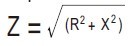
Z = Impedance in ohm per phase
R = Resistance at operating temp. in ohm per phase
X = Reactance in ohm per phase |
