| Photovoltaic Cables |
| 2PfG 1169 Photovoltaic Cables | H1Z2Z2-K |
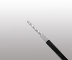
PHOTOFLEX Photovoltaic Cable
2PfG 1169 Photovoltaic Cables
 |
 |
Application
These cables are designed for connecting photovoltaic system components inside and outside of buildings and equipment with high mechanical requirements and extreme weather conditions.
Standard and Approval
2PfG 1169/08.2007 (PV1-F)
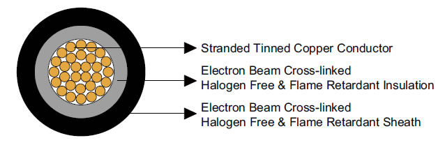
Cable construction
- Conductor: Stranded tinned copper conductor per DIN VDE 0295 and IEC 60228 Class 5.
- Insulation: Electron beam cross-linked, halogen free and flame retardant compound.
- Sheath: Electron beam cross-linked, halogen free and flame retardant compound, Black
Electrical Properties
- Rated Voltage U0/U: 0.6/1 kV AC; 0.9/1.5 kV DC
- Maximum Permitted DC Voltage: 1.8 kV DC (conductor/conductor, non earthed system, circuit not under load)
- Insulation Resistance: 1000 MΩ-km
- Spark Test: 6000 Vac (8400 Vdc)
- Voltage Withstand: 6500 Vac for 5 min
Thermal Properties
- Maximum Voltage: Ambient Temperature: -40℃ ~ +90℃
- Maximum Temperature At Conductor: 120℃ (20000h) according to IEC/EN 60216-1
- Short Circuit Temperature: 200℃/5 sec
- Thermal Endurance Test: According to EN 60216-2 (temperature index +120° C)
- High Temperature Pressure Test: According to EN 60811-3-1
- Damp-Heat Resistance: According to EN 60068-2-78 with 85% humidity
Mechanical Properties
- Minimum Bending Radius: 4×OD (fixed), 5×OD (flexing)
- Dynamic Penetration: According to 2 PfG 1169/08.2007 Annex F
- Notch Propagation: According to 2 PfG 1169/08.2007 Annex G
- Tensile Strength And Elongation Of Insulation And Jacket: According to EN 60811
- Anticipated Period Of Use: 25 years
Chemical Properties
- Ozone Resistance: According to EN 50396 part 8.1.3 Method B
- Weathering- UV Resistance: According to HD 605/A1
- Ammoniac resistant
- Very good resistance to oils and chemicals
- High wear and robust, abrasion resistant
- Acid & Alkaline Resistance: According to EN 60811-2-1 (Oxal acid and sodium hydroxide)
EC directives
- The cables are conform to the EC directives CE 2006/95/EC (Low voltage directive) and RoHS 2002/95/EC (Restriction of Hazardous Substances)
Fire Performance
- Flame retardant according to EN 50265-2-1, IEC 60332-1, VDE 0482-332-1-2, DIN EN 60332-1-2
- Low smoke emission according to IEC 61034, EN 50268
- Halogen free according to EN 50267-2-1, IEC 60754-1
- Low corrosivity of gases according to EN 50267-2-2, IEC 60754-2
Dimensions and Weight
| No. of Cores ×Nominal Cross Section |
No. of Stranding | Nominal Conductor Diameter | Nominal Insulation Thickness | Nominal Sheath Thickness |
Nominal Overall Diamater |
Nominal Weight |
| No. ×mm² | - | mm | mm | mm | mm | kg/km |
| 1×1.5 | 30/0.25 | 1.58 | 1.14 | 0.82 | 5.4 | 52 |
| 1×2.5 | 50/0.25 | 2.04 | 1.14 | 0.82 | 5.8 | 67 |
| 1×4.0 | 56/0.30 | 2.59 | 1.14 | 0.82 | 6.4 | 87 |
| 1×6.0 | 84/0.30 | 3.17 | 1.14 | 0.82 | 7.0 | 113 |
| 1×10 | 78/0.40 | 4.07 | 1.52 | 0.82 | 8.6 | 178 |
| 1×16 | 128/0.40 | 5.22 | 1.52 | 0.82 | 9.8 | 254 |
| 1×25 | 199/0.40 | 6.51 | 1.52 | 0.82 | 11.1 | 363 |
| 1×35 | 279/0.40 | 7.71 | 1.52 | 0.82 | 12.3 | 473 |
Current Carrying Capacity
| Cross Section | AWG | Maximum Conductor Resistance @ 20℃ |
Current Carrying Capacity | ||
| Single cable free in air | Single cable on surfaces | To cables adjacent on surfaces | |||
| mm² | - | Ω | A | A | A |
| 1.5 | 16 | 13.7 | 30 | 29 | 24 |
| 2.5 | 14 | 8.21 | 41 | 39 | 33 |
| 4 | 12 | 5.09 | 55 | 52 | 44 |
| 6 | 10 | 3.39 | 70 | 67 | 57 |
| 10 | 8 | 1.95 | 98 | 93 | 79 |
| 16 | 6 | 1.24 | 132 | 125 | 107 |
| 25 | 4 | 0.795 | 176 | 167 | 142 |
| 35 | 2 | 0.565 | 218 | 207 | 176 |
Conversion Factor for Deviating Temperatures
| Ambient Temperature ℃ | Conversion Factor |
| Up to 60 | 1.00 |
| 70 | 0.91 |
| 80 | 0.82 |
| 90 | 0.71 |
| 100 | 0.58 |
| 110 | 0.41 |